Timer Relay Wiring Diagram
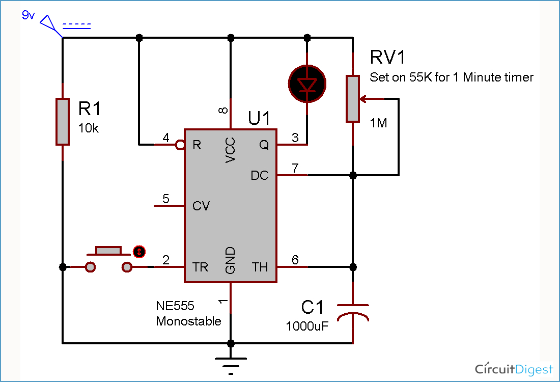
A wiring diagram usually gives guidance roughly the relative face and. For 5 min, 10 min and 15 min you just have to change the resistor value (r1).
60 Best Of Time Delay Relay Wiring Diagram
4 2.1 connecting 5amp timer.
Timer relay wiring diagram. It is an electrical component used in a circuit with a lower voltage or a smaller current to switch on or off a circuit with a higher voltage and larger current. At the end of the time delay (t), the output is energized. Ngk lamp timer 12v dc wire diagram need dentifying what ih8mud forum bj60glow ngk lamp timer 12v dc wire diagram sony ireleast info oe replacement parts.
Shows timers, tl is a pilot lamp timer of water temperature depending type, and w is a water temperature sensor. Ah3 delay timer and relay timer relay basic electrical wiring st01 delay timer electrical circuit diagram basic electronic circuits timer one transistor relay delay on timer circuit electronic circuit design circuit projects electronics circuit how to wire off delay timer electrical circuit diagram electrical diagram electrical wiring ah3 delay timer wiring with. Timer how to wire this delay relay switch electrical these diagrams came the circuit.
The 555 timer starts timing when switched on. This post is about the staircase timer wiring diagram in the diagram i use the on delay timer finder 8 pin relay re electrical circuit diagram timer diagram. 1993 jeep cherokee sport fuse box diagram 2008 chevrolet silverado fuse box diagram smoke alarm wiring color jeep cj coil spring conversion wiring schematic for 1966 chevelle fuse box acura mdx 2001 2003 duramax engine fireing.
The control points are pushbuttons with indicator lights (in order to be able to locate them in the event of extinction). Ah3 timer wiring timer basic electronic circuits home electrical wiring. Voltage, the time relay (t) upon application of input begins.
Angelo on october 13, 2021. With this kind of an illustrative guidebook, you are going to have the ability to troubleshoot, avoid, and full your tasks easily. During the circuit design with the timer relay and variety of timer configuration, questions such as
Double door fridge wiring diagram doubledoorfridgewiringdiagram in 2021 refrigeration and air conditioning air conditioner maintenance double door fridge. Relay can be the best option to control electrical devices automatically. 8 pin timer relay wiring diagram the electric timer allows a light point to be turned on from one or more places in the room, and to leave this light point on for an adjustable period of time.
240 volts ac and 480 volts ac are commonly used for these large pieces of. Get results from multiple engines. (nagoya, jp) a preheat timer connected to said on position of the engine key switch and.
Please look at this picture: Timer and contactor wiring diagram pdf. Not merely will it help you attain your desired results quicker, but also make the complete procedure less difficult for everybody.
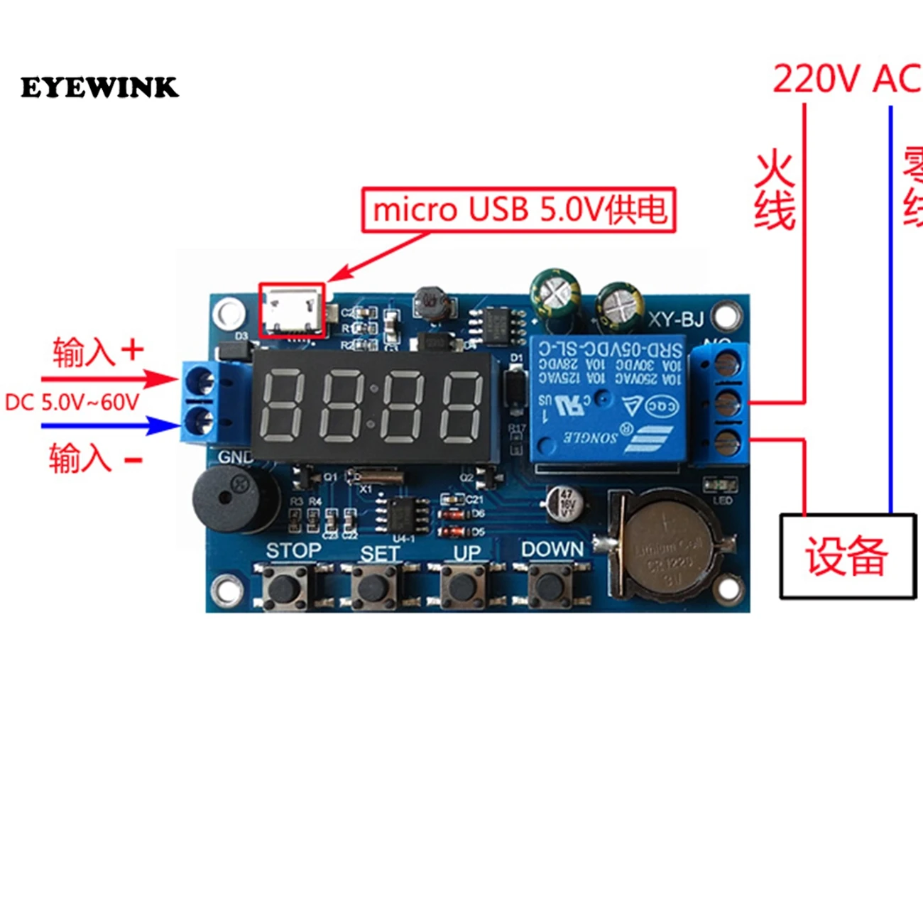
After one minute of time duration, the led will automatically turn on. 5 2.1 connecting 5amp timer. 8 pin timer relay wiring diagram | basic timer connection and function |three phase main distribution board wiring | 3 phase distribution mdb box wiring diag.
Ngk spark plug co., ltd. 5 pin is compromised of 3 main. Find instant quality info now.
Time delay relay wiring diagram how to wire pin timers for. It can be used for various switching. Time period can be calculated using formula t=(r1+r2)*c1.seconds when pot is maximum r is 120k+1.1m ≈ 1.2m (approximately) and c1=470uf t= 1.2m*470uf = 620 seconds≈10 minutes.this is the.
4b is a circuit diagram of a detector of the burning out of the glow plug; The square relay pinout shows how the relay socket is configured for wiring. The 555 timer starts timing when switched on.
The diagram above is the 5 pin relay wiring diagram. Junction (→ wiring diagram for basic unit,. With such an illustrative guide, you’ll be capable of troubleshoot, stop, and complete your tasks easily.
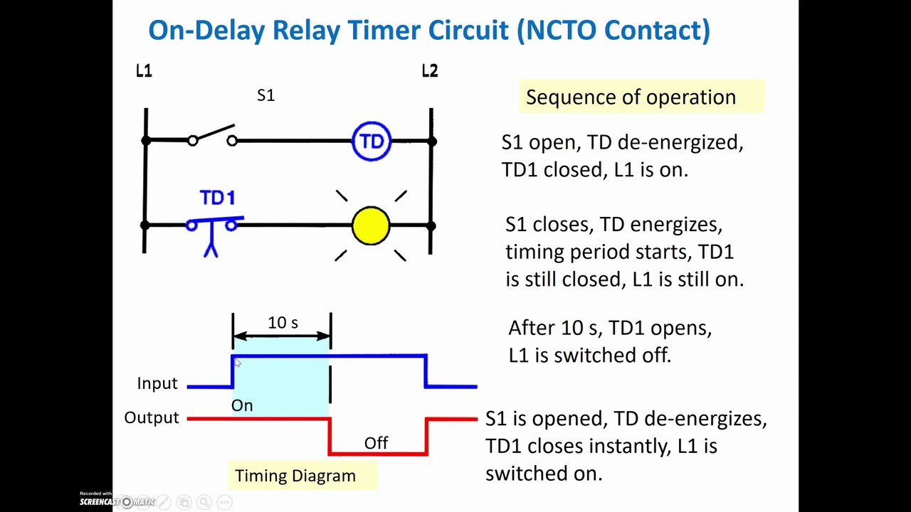
Off delay timer relay wiring diagram. At the end of the set time, the contacts transfer to the on state The timer function #1 is on delay, it allows to supply power after a period of time (t).
Eaton wiring manual 0611 5 2 contactors and relays 5 5 contactor relays contactor relays contactor relays are. There are different kinds of relays for different purposes. For example when a module will be powered up also it sends out a signal of fifty percent the voltage plus the technician would not know this he would think he has an issue as he would.
8 pin timer relay wiring diagram. Time relay refers to a kind of relay whose output circuit needs to make an obvious change (or contact action) after adding (or removing) the input action signal in a specified and accurate time. During the circuit design with the timer relay and variety of timer configuration, questions such what
Delay On Break Timer Wiring Diagram General Wiring Diagram

Time Delay Relay Wiring Diagram Download Wiring Diagram
Dayton Off Delay Timer Wiring Diagram Collection

timer How to wire this delay relay switch Electrical
20 Elegant Time Delay Relay Wiring Diagram
Irrigation Pump Start Relay Wiring Diagram Collection

Dayton Time Delay Relay Wiring Diagram A652

Solid State Timer Solid State Relay Timer Electrical
Timer Relay Wiring Diagram Gallery

Wiring Diagram Of Timer Relay RIAHSOSHI
30 Solid State Timer Wiring Diagram Wire Diagram Source
Dayton Time Delay Relay Wiring Diagram Free Wiring Diagram

Glow Plug Timer Relay Wiring Diagram SCRAPBOOKMAMAW

Dayton Off Delay Timer Wiring Diagram Collection

Staircase Timer Wiring Diagram Using On Delay Timer And

Dayton Time Delay Relay Wiring Diagram Gallery

Wiring Diagram Of Timer Relay RIAHSOSHI
Get Dayton Time Delay Relay Wiring Diagram Download

Delay On Break Timer Wiring Diagram