Gm Map Sensor Wiring Diagram
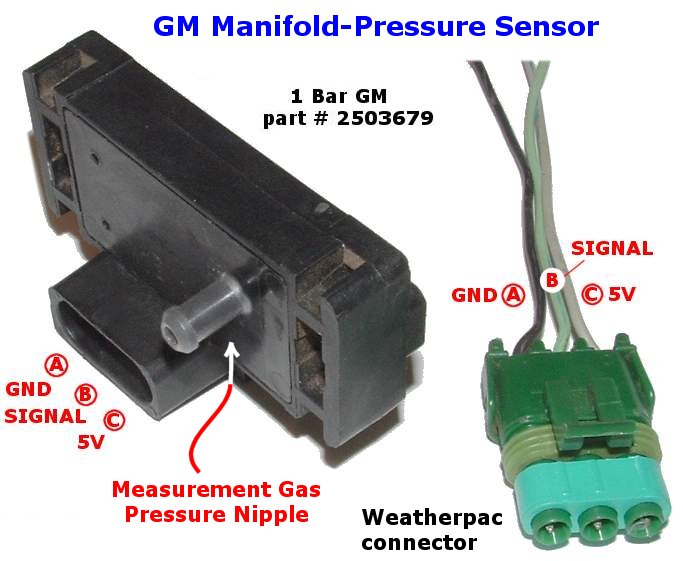
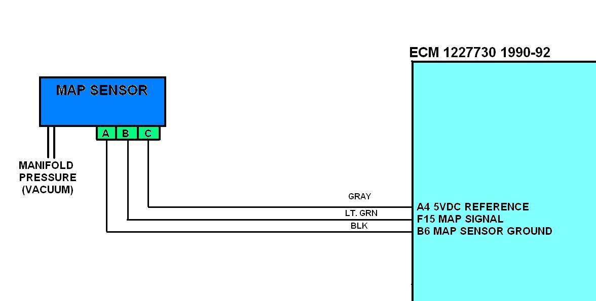
A map sensor measures the pressure in your intake manifold. All that is required is a vacuum hose from the intake manifold plenum to the sensor.
Manual Wiring Harness 1998 2002 GM LS1 / LS6 Drive by Cable Elect… in 2020 Ls engine, Gm ls

If not, the arrangement won’t function as it ought to be.
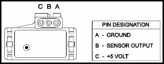
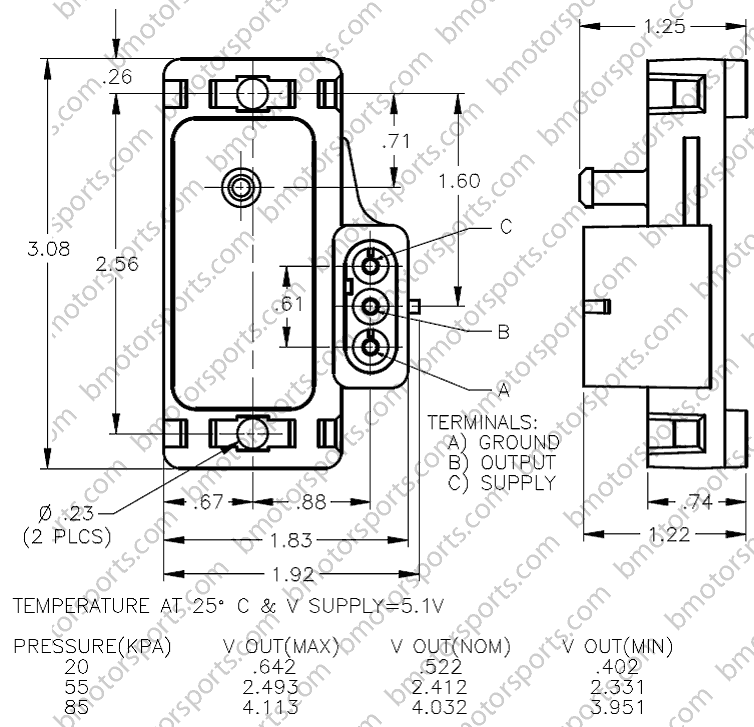
Gm map sensor wiring diagram. Check that you have 5.0 volts on pin #3 of the map sensor (counting from the square solder pad), and ground on pin #2 (less than 1.0 ohms resistance to the middle lead of the voltage regulator). Backprobe with a high impedance voltmeter at tps terminals a and b. The map connector that it came with, would not work with my gm sensor 12592525 3 bar.
In this article, we also have variety of pictures usable. I did rewire it but it was not in the same wire location i wired it per the gm directions which i will list below. Wiring diagram is a technique of describing the configuration of electrical equipment installation, eg electrical installation equipment in the substation on cb, from panel.
If you run into an electrical problem with your gmc, you may want to take a moment and check a few things out for yourself. One will be ground, or 0 volts. Oil sending unit wiring third generation f body message boards.
At normal sea level, the map sensor signal on the board (pin #1, the pin closest to d4) will be 1.75 to 1.80 volts. Verifying the map sensor has power. Probe the terminals of the map sensor to check for proper reference voltage.
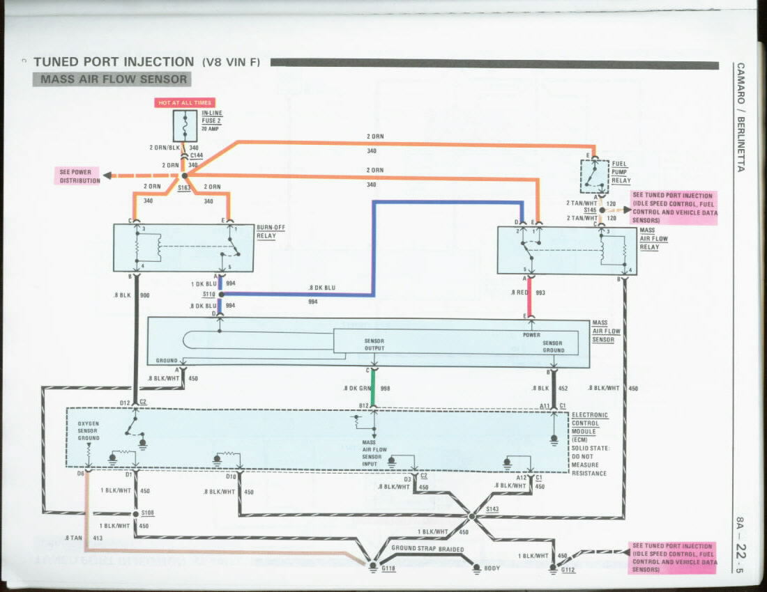
General motors tuned port (5.0l and 5.7l) injection engines. Angelo on october 3, 2021. Thank you for reading gm crank sensor wiring diagrammerely said the gm crank sensor wiring diagram is universally compatible with any devices to read.
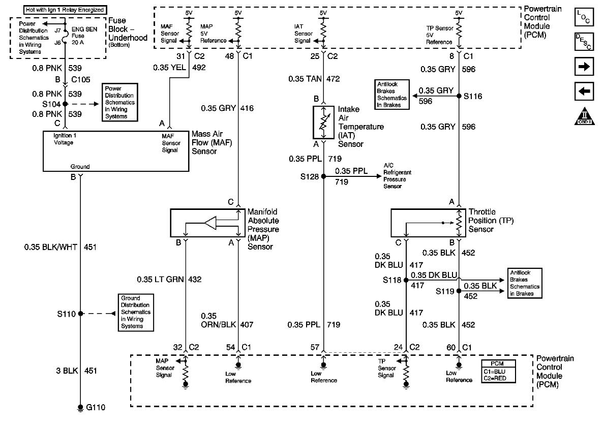
Manifold absolute pressure (map) sensor wiring diagram. But for some reason i had 325 volts from the signal wire which is the greenred wire. I hooked up my 3bar gm map sensor using the above wiring diagram.
Map = manifold absolute pressure. Testing the map sensor with a multimeter. Verifying the map signal with a multimeter.
Wiring diagrams repair guide i have a 2002 chevy cavalier and bought air conditioning chevrolet transmission sd engine performance cheve the c 2000 diagram electric radiator s10 4 3 can fuse installation chevy cavalier and pontiac sunfire 1995 2000 wiring diagrams repair guide autozone i have a 2002 chevy cavalier and bought oxygen sensor […] It is a variable resistor that varies resistance in proportion to absolute pressure and sends nominally a 0 to 5v signal to the ecm. The ls1/ls6/ls2 map sensor (bottom left) is sealed to the intake manifold with a rubber seal.
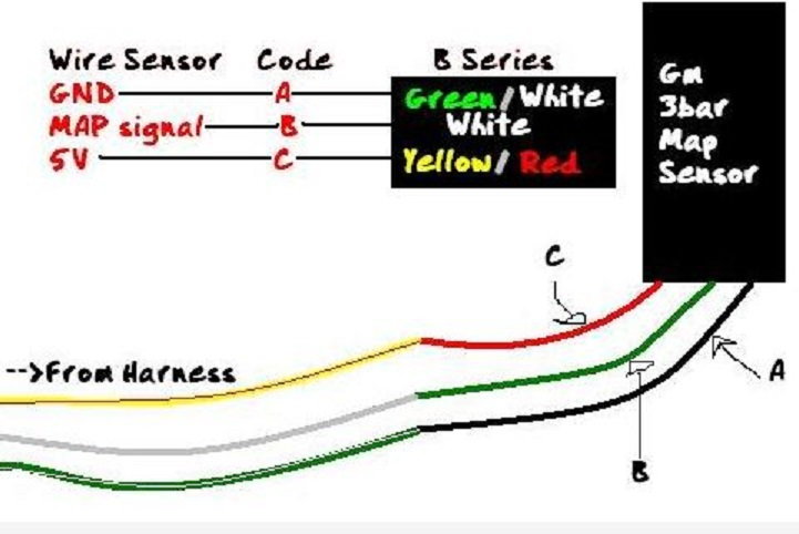
Gm 3 bar map sensor wiring honda ――――. Tps testingsee figures 2, 3 and 4. Map sensor output based on altitude (ignition on and engine stopped) gm 1bar, 2bar, 3bar.
Map sensor test (p0106, p0107, p0108) (gm 4.3l, 5.0l, 5.7l). We have 8 photographs about chevy 454 firing order including images, pictures, models, photos, and more. A map or a maf will have 3 wires.
Colors are the harness and numbers are. Instructions i recived with mine: Such as png, jpg, animated gifs, pic art, logo, black and white, transparent, etc.
Gm 3 bar map sensor wiring diagram. This includes all wiring that is needed by the computer to run and control the fuel injection system. Gm 3 bar map sensor wiring honda whats new.
Around 332v 294 psi 2 bar of boost or 3 bar for the sensor. Gm duramax map (manifold absolute pressure) sensor wiring harness, harness only sensor not included. Maf = mass air flow.
Weld the boss in place before installing the sensor. I was able to get a new connector but trying to know if anyone has had this problem? Chevy 454 firing order chevy 454 firing order chevy 454 firing order which you are looking for is can be found for you on this website.
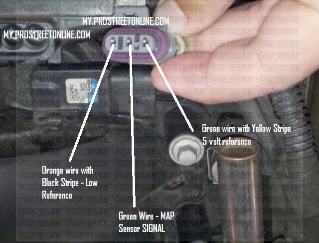
Gm 3 wire oil pressure switch wiring diagram. 1 psi = 2.036 of mercury (hg) 1 mercury = 0.4911541 psi. One will by 5 volts, which powers the device and is supplied by the ecu.
Diagram autometer electric oil pressure gauge wiring diagram full version hd quality wiring diagram toyotadiagrams andreapendibene it. I have a new dominator efi system. Gm 3 bar map sensor wiring honda ――――.
Lly duramax engine sensor diagram also oil leak intake after map sensor along with freightliner fl80 wiring diagram furthermore gmc build furthermore lb7 fuel system parts breakdown list together with c parts moreover duramax crank sensor location further duramax sel engine oil along with 6 0 powerstroke icp sensor location also along with n2. But if you don't have a wiring diagram, you can still find your signal wire by measuring it. Discussion starter · #12 · apr 24, 2006.
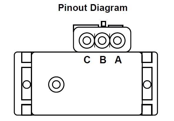
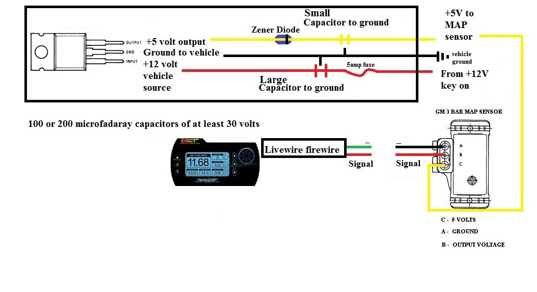
Each part should be placed and linked to other parts in particular manner. The map sensor has a three wire connection to the ecm consisting of a 5v reference, ground, and a signal wire. The early gm map sensor (top) has a provision for being mounted just about anywhere it fits.
Gm 3 Bar Map Sensor Wiring Diagram
Gm Maf Sensor Wiring Diagram Wiring Diagram Schemas
MAP sensor wiring LS1TECH
Gm 3 Bar Map Sensor Wiring Diagram
Forum View topic GM MAP sensors
Repair Guides Carbureted Electronic Engine Controls Manifold Absolute Pressure (map

Toyotum Map Sensor Wiring Diagram Complete Wiring Schemas
Wiring your GM Map Sensor / IAT Sensor for use with a 'CSL' clone ECU ECUWorx
Repair Guides Fuel Injected Electronic Engine Controls Manifold Absolute Pressure (map

Gm 3 Bar Map Sensor Wiring Diagram
MAP Sensor wiring colors GMC Acadia Forum

Gm Maf Sensor Wiring Diagram Wiring Diagram Schemas
How To Install a 3 BAR MAP Sensor My Pro Street
UZL Gm 2 Bar Map Sensor Wiring Diagram doc download Read Book
Gm 3 Bar Map Sensor Wiring Diagram
issue wiring in gm map sensor for lw.
Gm Maf Sensor Wiring Diagram Wiring Diagram Schemas
2001 Chevy Silverado Knock Sensor Wiring Diagram Free Download Cars Wiring Diagram Blog
3 Bar GM map sensor BLUES... AGAIN!!!! Miata Turbo Forum Boost cars, acquire cats.